Author: Kas Oosterhuis | 2014
Director ONL [Oosterhuis_Lénárd] | Professor Hyperbody Department of AE&T Faculty of Architecture TU Delft
Abstract
We are living inside evolution. There is nothing more exciting than to realize that the billions of components which constitute today’s built environment are subject to continuous change and evolution. Specifically in the building industry the major game changer is the shift from mass production methods to made to measure processes for the masses. Now both the production industry and the individual makers can produce series of unique nonstandard components cheaper and better than the earlier series of the same which earmark the building boom we have left behind us. This paper addresses the implications of the long tail of the building industry revolutionizing the next generation buildings. Buildings will never be the same, there will no more repetition of components from a catalog, each design will create its own families of uniquely shaped parametric building components, uniquely behaving distributed climatic de- vices and personalized interaction apps effectuating the movements and intentions of the users in real time. The next generation building is fundamentally generic, following simple rules as to generate complexity, based on open design systems, its design being inherently participatory and inclusive. The actuating climatic and structural building and interior components cooperate with their identified users as in a swarming hive of things and people. The author illustrates the game change with built examples from his own design practice and with examples from his university based research group.
Keywords: game change, evolution, mass customization, made to measure, tag, identity, nonstandard, makers, the long tail, next generation, parametric, top down, bottom up, swarm behavior, distributed, climate design, structural design, personalization, preferences, body, styling, powerlines, feature lines, vectorial, drivers, data exchange, lean, app, real time, fundamentals, rule based, generic, generative, algorithm, complexity, open design system, design game, participation, interaction, actuators, actor network, hive, inclusive.
1. Generic < > Specific
First of all there is an urgency to rethink the understanding of the word generic in relation to architecture and urban design. The word generic has been popularized by Rem Koolhaas in the nineties and many, including Koolhaas himself, have misleadingly interpreted the generic into a supposedly objective aesthetics for architectural design, while in a populist fashion being offensive to other design attitudes, and blaming them to be specific. Therewith suggesting that generic is good, and specific bad, implying that architects who choose a different path are simply wrong. Such method of communication is straightforwardly populist, very similar to those populist framing, naming and blaming debating techniques that we all too often see in politics today.
Synonyms for generic are among others are, according to a google search: general, common, collective, non-specific, inclusive, all-inclusive, all-encompassing, broad, comprehensive, blanket, umbrella, sweeping, universal. Let us apply the meaning of the
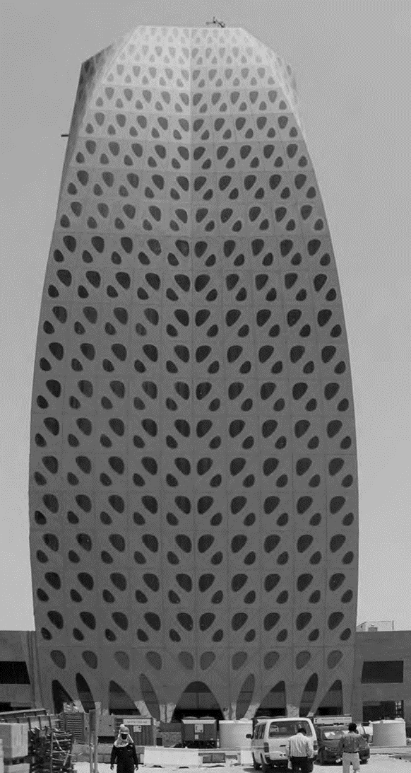
Figure 2. ONL | LIWA tower | 2013
word generic now on the distinction that is made between geometrically simple shapes and geometrically complex shapes. Which one of the two is the generic, and which one the specific. In common understanding, and exploited by OMA and their numerous offspring like MVRDV, Neutelings, DKV, KCAP, BIG, the simple platonic shapes are considered generic and for the common people, while the nonstandard geometry is considered to be specific and elitist. I will contradict the above populist reading and argue for the exact opposite understanding of the terms generic and the specific.
It is hard if not impossible to describe complex shapes starting from simple platonic forms. One will have to add, rotate, scale, chamfer and fillet thousands of iterations before something could have been achieved that comes close to a complex shape. And it would certainly lack intelligence and internal consistency, it would simply be an series of arbitrary actions to produce something that only superficially will look like complexity. From the other perspective, from the point of view of complexity theory, it is easy to describe a simple rectangular shape, simply by drastically reducing the number of reference points. Typically a box has eight vertexes to describe the box, while a complex doubly curved volume may require thousands of vertexes to properly describe the shape. The point to make here is that the complex shape is intrinsically inclusive since it includes a possible description of a simple box, while the simple platonic shape is exclusive in its nature—and hence elitist—since it excludes any possible description of a complex shape. The platonic volume must therefore be seen as a specific instance of complexity. Hence I must conclude that the nonstandard is generic and the platonic specific. Hereafter I will take it one step further and will argue that true complexity is based on simple rules, complex but not complicated.
Let me illustrate the above statement that the nonstandard is the true generic with two examples, one benchmark design by Ludwig Mies van der Rohe, and my own recently realized design for the LIWA Tower in Abu Dhabi. I am great admirer of Van der Rohe, I will reflect on his work in the context of his time, which is to me the proper way to do. Implying that I would not even consider of superficially copying any of his designs or parts of his design, neither try to re-interpret his work with the technologies of today. Instead I look at the technologies that are available to us today and draw my logical conclusions to establish an internal logic and stylistic language that is in synch with the spirit of today. Van der Rohe’s Seagram Building in Manhattan in New York [1958] is an uncompromising elegant expression of mass production methods, therewith capturing the fascination of the times, building that new immaculate world leaving the scars of WW II behind. Now we live in years ten of the 21st Century, that is 64 years or 2–3 generations later, and we live in a different world, new technologies shaping our daily lives. The end of the fifties were characterized by the rise and shine of television, and the invention of the integrated circuit [Kilby 1958], which effectively provoked the age of computation. The early decades of our century are flooded by easily available computational design techniques and computer numerical controlled fabrication techniques that are taking advantage of the computing power of powerful microchips. The LIWA tower in Abu Dhabi which my office completed this year is exemplary for the potential of parametric design techniques and mass customization production techniques, brought to live by an uncompromising design concept and an well developed opinion on the shaping of the building body imposing fluid powerlines on the point cloud of reference points constituting the DNA of the structural skin. Now seen from the technological and social perspective of today, if we would model the generic inclusive approach of the fifties, as represented by the Seagram Building, in a systemic parametric design, we would actually voluntarily cage ourselves in one specific instance of thousands parametric possibilities, falsely justified by a nostalgic feeling for the beauty of the past. The method of scalable mass customization is a game changer.
2. Complex < > Complicated
Although Frank Gehry is widely praised for his contribution to nonstandard archi- tecture, his realized works show very little of that. Basically he was and remained deconstructivist in his design attitude, not nonstandard. The design process in Gehry’s office would typically develop as follows: 1] a loose but traditional arrangement of functional blocks would form the basis for the project, satisfying the functional needs of the client. In another room many paper models are made as to wrap around these functional volumes, typically not wrapped all around, but only partially as to generate at least one intriguing view fit for publication in the architectural magazines. Then the paper models are digitized with a 3d digitizer, snapping at points on the surface of the crushed silvery paperwork. These points are then conveyed to the 3d modeling program Digital Project and from there entrusted to Autocad. The complexity of this process hardly deserves to be understood as complex but must be considered complicated instead.
For a proper understanding of the silent yet deep revolution that is taking place in the building industry, motivated by the rise of digital media, social media and industrial mass customization, it is necessary to make a clear distinction between the complex and
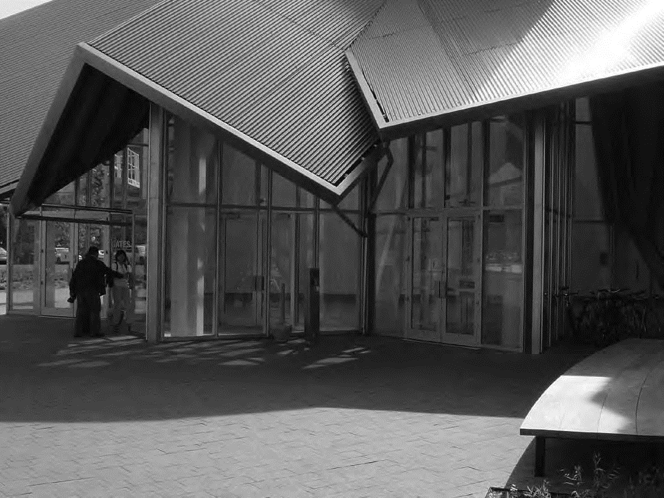
Figure 3. Gehry | entrance Stata Center | 2004
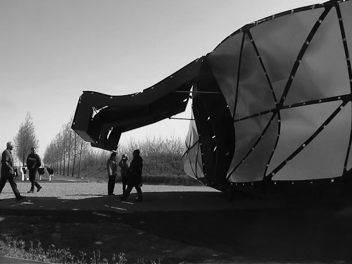
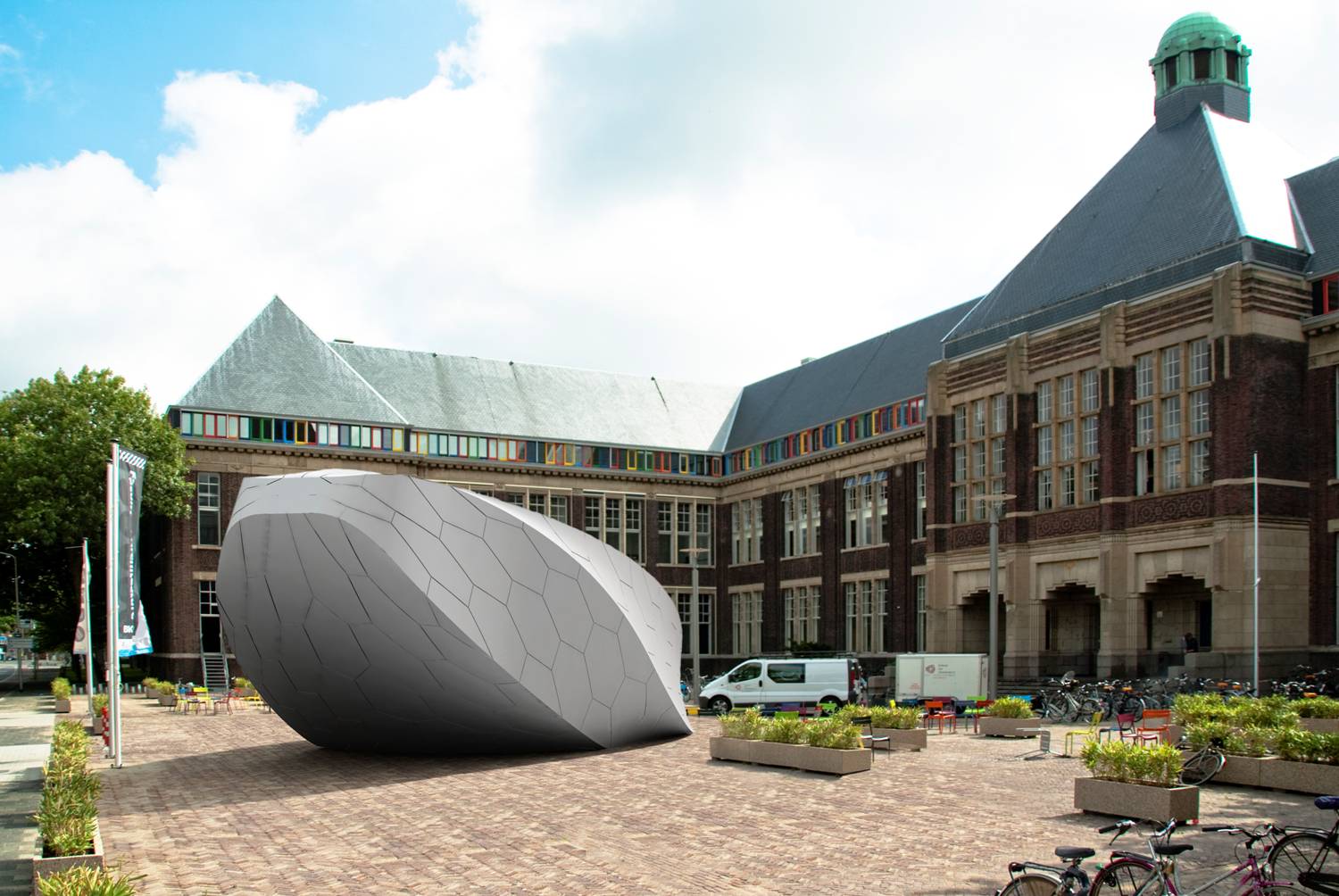
Figure 4. ONL| iWEB entrance | 2002
the complicated. Where complexity based on simple rules that take control of the complete project, complicatedness is the compilation of ad hoc solutions for each corner of the project. Complexity is where the exception freely exploits the rule, while complicatedness suffers from a multitude of laborious exceptions to standard products. In complexity de- signs where all constituting parts are interconnected and interwoven, where the details are developed as specifications of a basic building component. For example in the design for the iWEB the canopy doors are a specification of the generic node detail. For the iWEB the door is not imported from a building catalog as in the case of the entrance of the Stata Centre, but stems directly from the parametric design system. Complexity is generic, complicatedness specific. Complexity is inclusive, while complicatedness is deeply rooted in the standard and hence discriminatory with respect to the nonstandard. Complexity based on simple rules is a true game changer.
3. Component < > Composition
Traditionally the education and profession of architecture circles around the mythical properties of the architectural composition. When one starts thinking of any spatial arrangement as a composition, one voluntarily chooses an immaterial programmatic top-down view on the project. In digital design circles at the other hand it is the tweaking of parametric patterns that takes on mythical properties. This other view, which is generative in its nature, considers the construct as a build-up of varying interconnected building components, composing an emotive experience in space, usually along a predefined trajectory. I will argue here that neither approach alone can cover the complexity of any design task for a built construct. The bottom-up component approach should ideally be developed in a bipolar relationship with the top-down composition. The stronger the assumed polarity between composition and component, the stronger the potential for a strong conceptual force in the design. Bottom up individual character builds up inside a top down informed open design system. The wider the bandwidth between bottom up and top down the more excitement may be created in playing by the rules.
The development of parametric building blocks that are suited for the larger scale of building however is hardly touched upon in parametric circles. I have seen, especially in academic environments, a multitude of porous pavilions being designed, produced and assembled, along with a multitude of parametric organic fantasies, without any relationship to the actual building technologies that are badly needed to be developed in order to process the construction of larger building complexes. Typically in any Gehry design the parametric strategy is limited to the complicated loose wrappings around otherwise traditional spatial designs, built according to traditional building methods like in situ cast con- crete, welding on site, and worst of all on site plaster works finishings. In Gehry’s designs there is not a smart and lean relationship between structure and skin, let alone between skin, structure and interior finishing. Therefore the Gehry designs loose their conceptual strength completely when it comes to the bipolar relationship between composition and component. In Gehry’s designs the traditional composition rules, the constituting components of the skin are subordinated to its banal composition, failed to be integrated into the structural design, and hence clueless and nothing more than decoration.
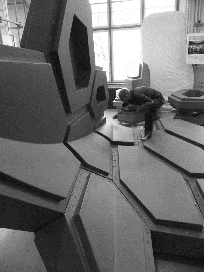
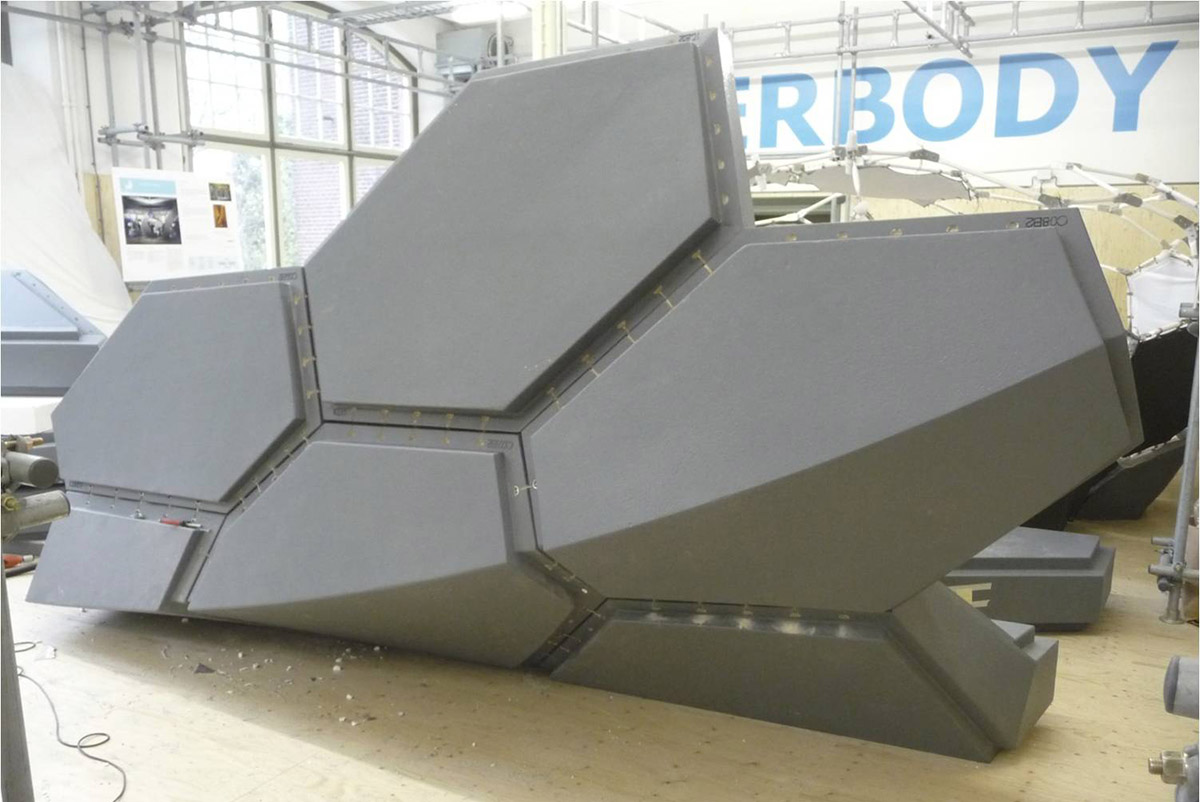
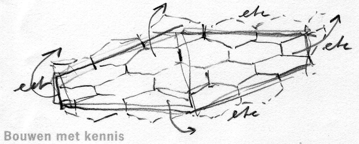
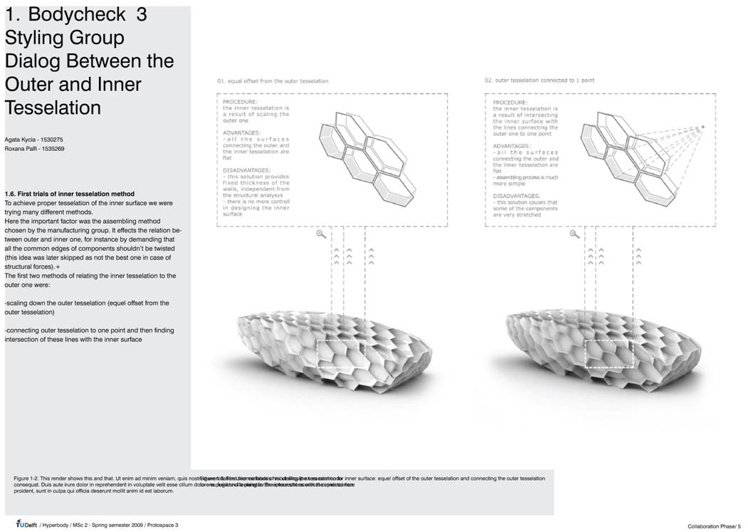
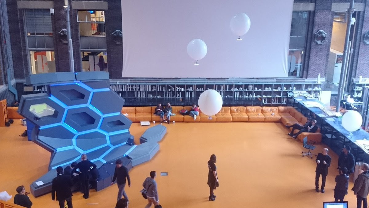
Figure 6. Hyperbody | Parametric building blocks MSc2 project | 2009
This polemic essay aims at arguing for an even further integration than that of structure and skin, I advocate the design of building components that are semi-permeable skin, load bearing structure and climatic performative in one. Once such full fledged integration is reached, its naturally will be charmingly decorative as well in its detailing, with- out the need for a separate decorative layer. Ideally structure and skin work together as to transfer the loads, ideally each building component performs a specified programmable task as to bring in fresh air, pump out spoiled air, generate heat or radiate coolness, filter particles, let in daylight or light up using LED lights. Ideally the entire building consists of interconnected families of specified building components, each of them acting/performing locally and interacting with the changing weather conditions at the exterior side of the skin, and with the whimsical needs of the users at the interior side. Ideally each building component is part of a parametric family finding it own dimensions, shape and weight as to per- form generously within its local context. Necessarily each building component is scripted in the design phase, CNC produced as to be mass customized and produced cost-effectively. Logically each building component would have its own identity and brains as to act locally and as to communicate with their nearest neighbors in real time, continuously updating its current state and informing its closest environment about that current state. The good news is that such ideal building component is a definite reality, since it can be made by thoughtfully applying currently available technologies, and that it can be achieved within standard budgetary constraints. Buildings which are in their entirety composed of interacting swarms of performative mass customized building components definitely represent a game change. The sad news however is that the processes that are necessary to achieve this are heavily compromised by the traditional way larger buildings are currently financed, programmed, designed, tendered, produced and managed. I will enlarge upon this issue in another essay, but it has to be mentioned here as to avoid picturing an overly optimistic scenario.
4. Actor Network < > Grid
The above described unique performative building components form an actor network, as opposed to a tessellated grid that organizes a collage of largely identical elements ordered from a building catalog. In the network the nodes are the actors that are connected
Figure 7. Manhattan grid
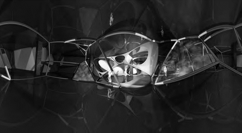
Figure 8. ONL | Digital Pavilion Seoul | 2006
to each other via the edges, in the grid the fields inside the grid lines are isolated objects with no relation to each other. The design concept I am looking at when declaring that the components of the next generation building embody the best of both of these worlds. The grid, turned into a non Euclidean parametric tessellation, allows for a specific performance of each embraced field within the grid. While the edges of the components may form the structural connections between the nodes, the centers of gravity of the enclosed fields may constitute the network of wirelessly connected, interactive, sensitive components, in its essence similar to the individual high rise jutting out of the Manhattan grid system. “Maybe their very lack of character provides the best context for living” (R. Koolhaas, Wired, 1996). Koolhaas argues for a generic grid that allows individual well-being and growth. The critique I have on his seemingly self-evident statement is that Koolhaas retroactively uses the grid and what is contained inside the grid as a formal language. The open parametric design system, which is based on the higher level nonstandard grid that I am propagating here is in a flexible way adaptive to externally changing circumstances, and internally open to the individual acts of owners, clients and users.
The theory and practice of actor networks in the built environment is surprisingly enough almost literally described by Marvin Minsky in his book The Society of Mind (1988), but then projected on the human brain and its connections. Minsky constructs a model of human intelligence which is built up from the interactions of simple parts called agents, which are themselves relative simple, while their interactions constitute the society of mind. Interestingly the words and descriptions Minsky uses to describe his theory resonate almost 1:1 with the words and terms I am using to describe our agent based smart building component system. Now replace the agents of the human brain with the information processing building components, and it is immediately clear that Minsky’s insights potentially means a true revolution when mapped on the theory and practice of the next generation building. The notion that the building is a society of agents, as opposed to a formal system like a grid system, in nothing less than a game changer. The interacting building components form together in all their complex relationships the society of body. I no longer consider to add brains to the building body, but consider the building to be the brain.
5. Open Design System < > Proprietary design
My office has been experimenting with open parametric design systems for more than a decade. In 1998 I designed the Attractor Game as an open design game which enables to play with the parameters as to define an urban plan for 1500 homes in Groningen. Designing an architectural game means setting the rules which can be played by myself and by others as well. Compare it to a tennis game. Some inventive mind at a certain moment in time has proposed the rules of the game, to be played by anyone, amateurs and professionals alike. The level of the skills of the player is decisive for the attractiveness of the outcome of the game as executed. Exactly like this I foresee that the profession of architectural design will evolve. The expert formerly known as the architect [The Expert Formerly Known As The Architect, Linkedin discussion group initiated by the author in 2010] opens up the design process to clients, to college experts and to end-users as well. Basically everyone who is in one or another way involved in the development of the design is a valuable player, a co-designer, a co-creator, playing by the rules as set by the game developer. Even the expert formerly known as the quantity surveyor becomes a designer in its own right, since he/she has quantifiable influence on the outcome of the design game, he/she becomes the quantity designer. Open design designs systems are here set against traditionally proprietary design practices, where the single lead designer claims full authorship, regardless of how much
Figure 9. ONL | Attractor Game | Groningen 1998
Figure 10. ONL | grasshopper information feedback | Climbing Wall Amsterdam | 2012
actually is decided by this designer. The distribution of authorship right has to be reconsidered, and even more relevant, the architect has to redefine its expertise. What exactly is the authority of the architect in a multi-player design environment? A broader discussion on this subject is badly needed, but falls beyond the scope of this essay.
The design of the rules of the game may be an open design process as well. Open source techniques are available to develop the rules on an open programming platform, where invited and/or self-invited individuals contribute to the scripting of the rules. The open source society has not yet produced convincing examples of open source design. The best examples are momentarily seen in the automotive industry, the building industry probably one of the last industries to follow. The open design system must be accessible for all, clients and users participate in the design game as experts and are considered equal to designers, engineers and marketeers. Any building becomes a personal MyBuilding in the eyes of every participant in the open design game. Anyone who participates acts per definition locally and feels him/herself to be the center of the design universe of that particular moment in time that he/she is acting inside the game. One is either in the game or looking at the game. While traditional participation largely is limited to raising voices and commenting on a closed process, true co-design and co-creation means that one is in the executable process of the game. Such participatory design is a true game changer for the profession of architecture.
6. The expert formerly known as the architect [TEFKATA] < > the master builder
I believe the most important question architects must ask themselves today is: what exactly is my expertise? Am I that generalist, known as the master builder, who knows a little bit of everything, as is still propagated by the majority of academic educators? Or am I the specialist, being the expert in a specific field of knowledge? And if so, what exactly could that field of knowledge be? It may be clear that I advocate the second option, being a specialist. But a specialist in what? In any case, the TEFKATA will be one specialist acting in a swarm of many other specialists. Anyone whose knowledge and experience has influence on the size, material, structure, shape, production, assembly, climate, performance, costs and user management of the built construct, must be considered to be a designer, proportionally to its available or acquired budget authorized to make decisions. Such a specialist is an expert designer, in a team of other experts. All of these experts have their own opinion, but limited to the field of deep knowledge they represent. All of these experts must respect the authority of other experts, as they are respected themselves by the others. The traditional master builder would claim to know how many of the other fields of knowledge must be integrated to form a consistent whole. But is that true? In my 301 years experience as a practicing architect I have seen many other experts of other fields being perfectly capable of doing that as well, many of these experts are well educated and have a good understanding how things may be integrated. I think the integration will come from the swarm when all individual experts communicate in a 1:1 bottom-up fashion with their nearest neighbours. This will lead to much more consistent piece of work than when there is top-down 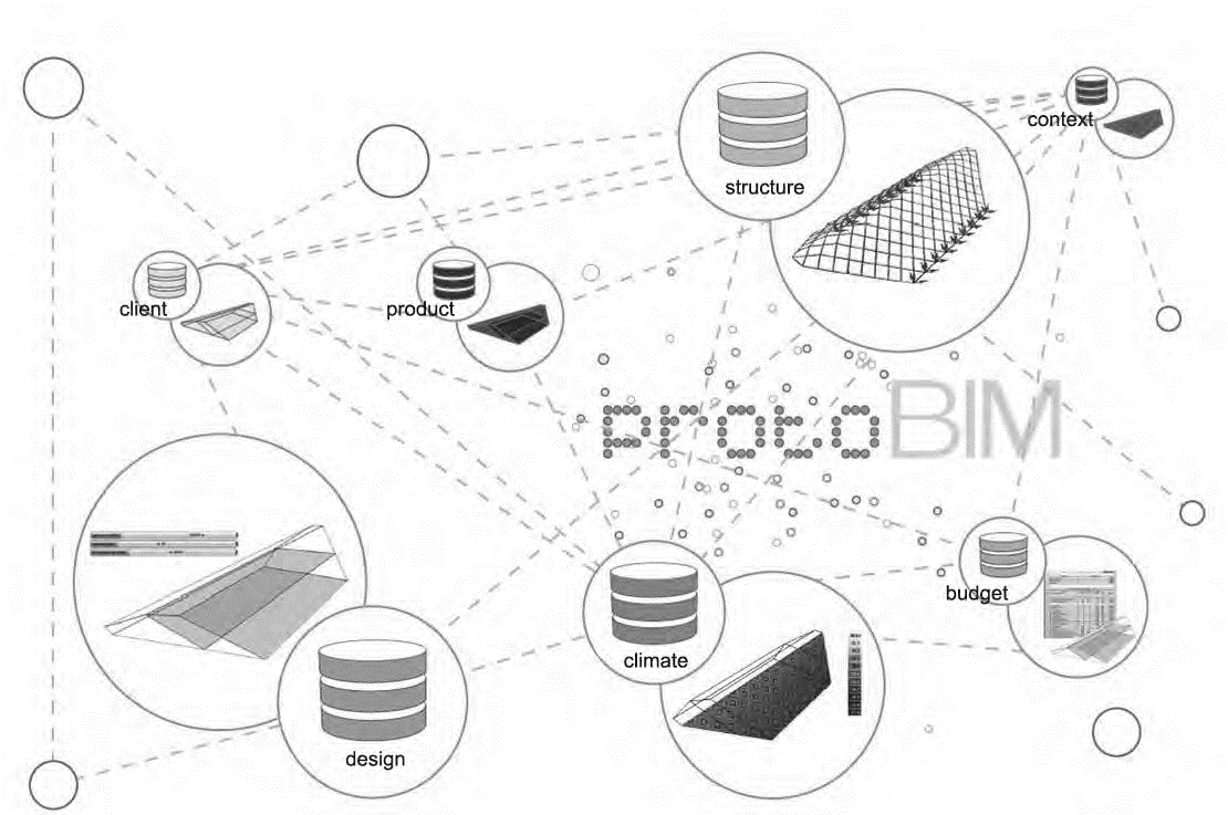
Figure 12. ONL |protoBIM |diagram data-exchange between experts | 2010
puppeteer leader, who imposes his/her limited knowledge on experts with more knowledge in their own fields. In the swarm picture there is not one leader, but a rotating leadership. All experts would in principle move freely in relation to each other, taking pole position alternately one after the other, taking advantage of the lee side by letting someone else do the hard work in the forefront position. Just like in any group contest there will be a winner in the multi-player design game, which is the one who plays his/her cards on the most strategic moments, which is the one who plays the game most skillfully. But in principle they start as equals and at the same time. It is crucial that the team should be established as from the very beginning of the process of developing conceptual ideas and specialized designs. To reach this goal the contractual client consultant relationship and the tender procedures be must reconsidered.
The TEFKATA must find its expert niche in the new way of collaborative design and engineering. In the Hyperbody master design courses I typically organize the brief in such a way that the students, work in groups of 4–6 people, and that each student chooses an expertise. The student then for a number of weeks looks at the project from the viewpoint of this field of expertise. For example the shaper, which is the person that gives shape to no matter what, would look at the form and styling of any building component, including structural and climatic components. In fact this student must develop an opinion on the shape and the style. When the student would choose to be the material expert, he/she would dive deep into material aspects of all constituting components of the built construct. It is clear that one single student would never be able to dive that deep in all different aspects of something as complex a the built environment, it is too big for one student to handle and to excel in all finesses. Typically during one semester I stimulate the students to swap roles, as to see the project from another point of view, and be very serious and ambitious about that new role. The TAFKATA definitely is a game changer.
7. Least common multiple < > Greatest common divisor
Just there, just that, just then, just thus. This could very well serve as the leading motto for the leanest possible form of data-exchange between the experts in the multi- player design game. The ambition is to exchange no more data than is strictly necessary for the connected expert to perform their task.
I was much impressed by the Apollo-Soyuz connection which took place on the 17th of July 1975, for obvious reasons. The less obvious reason, but the only relevant reason in the context of this essay, is the shear elegance and lean nature of the connection. Americans and Soviets needed to agree on only one connection, the technology and the
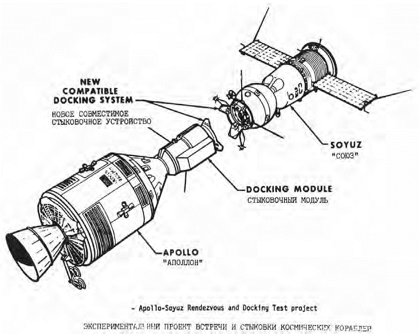
Figure 13. Apollo-Soyuz connection | 1975
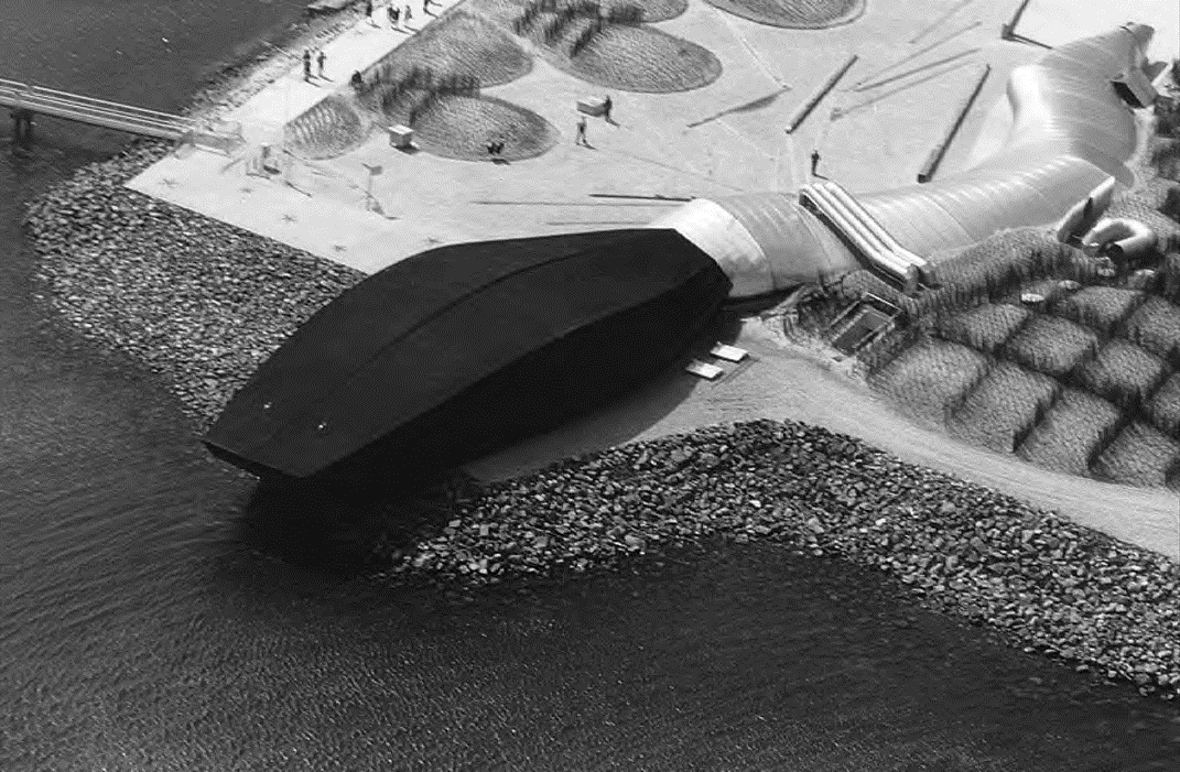
Figure 14. ONL / NOX | Waterpavilion connection | 1997
diameter of the docking ring. The two spaceships were of completely different design, on all those aspects the Americans and the Soviets did not have to agree at all, only the docking ring matters. It clarifies the meaning and importance of lean data exchange. In order to cooperate they did not need to exchange their complete BIM models, but only the details of the ring instead. How elegant, how essential. When it came to find a basis for cooperation between ONL and NOX during the early design process of the Waterpavilion at Neeltje Jans [an artificial island between the impressive sea barriers], we decided to minimize the amount of items to agree upon to that which was strictly necessary to connect. It was agreed to meet in one common ellipsoidal section, whereas ONL would cover the ellipse at the outside, and NOX would slightly protrude at the inside as to materialize the connection. That was all, there was no more direct collaboration than common presence in meetings with the client Rijkswaterstaat. The interesting observation during the opening party was that the public did not seem to notice in the interior the transition between the silver grounded beast of NOX with the black stranded sculpture. Both sides were so special and unique in their design approach that it was experienced as a continuity, just like the internal transition from Apollo to Soyuz.
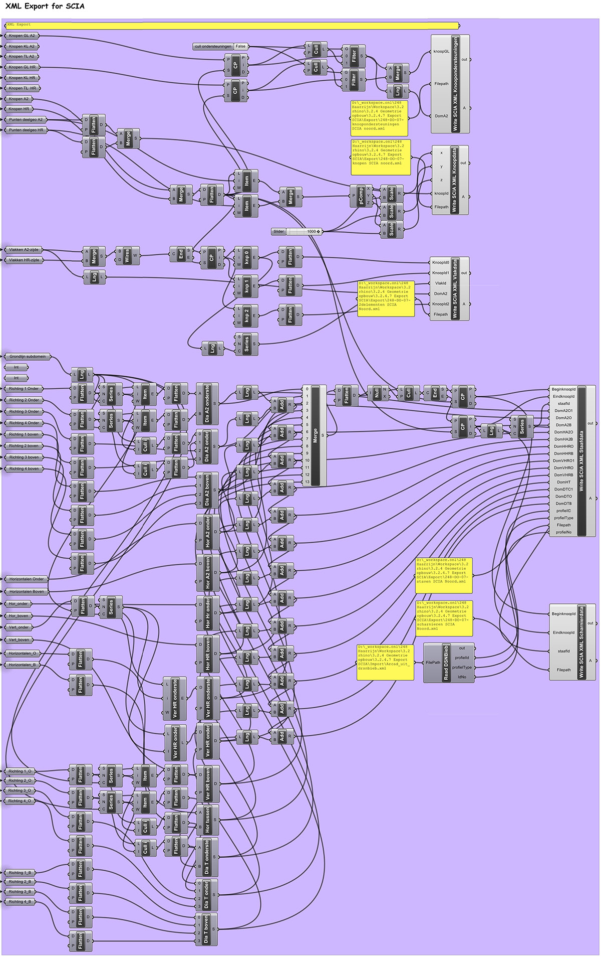
When exchanging data with the structural engineer, I give them only reference points and/or reference lines [data in the form of coordinates], and some metadata, which may label a node as moment fixed or hinged, or describe a surface enclosed by the reference lines as closed or open [capturing loads / wind loads or not]. Before starting the design work

Figure 15. Star Wars Death Star attacked by Luke Skywalker, |“Feel the Force”
I sit together with the engineer precisely what data can be read directly into their software, and then I export only those data, and certainly not the complete BIM model of my design. In fact I share as few data as possible. I share just the least common multiplier of data, as opposed to the greatest common denominator that is shared in the traditional linear design development chain. I share just that. This principle of lean data sharing characterized the lean data exchange process, in all phases of the design development. When exchanging data to the CNC machines one exports only those data which are read and understood by the CNC machine, just that. That machine produces just that unique building component that fits only just there, and is assembled on site just then.
Luke Skywalker just then intuitively pushes the button as to destroy the much hated Death Star [Star Wars Episode VI, 2005], the image of which has been without doubt inspired on the massive bronze spheres [1963] by Italian sculptor Arnaldo Pomodoro. Skywalkers’ intuition has been extensively trained as to feel the force. Similarly to be able to fit unique building components just there and just then, it needs a solid preparation in the parametric open design game. Such precision provides for the justification to perform exactly like that at that particularly moment in time and space, which is why the building component must act just thus. The just there, just that, just then, just thus strategy is the ultimate game changer to redefine the very nature of the design game.