008 | Palaisquartier Frankfurt

Maasimiliano Fuksas | alaisquartier Frankfurt | serious mistakes in the geometry of steel structure leads to messy welding of the nodes

Messy welding

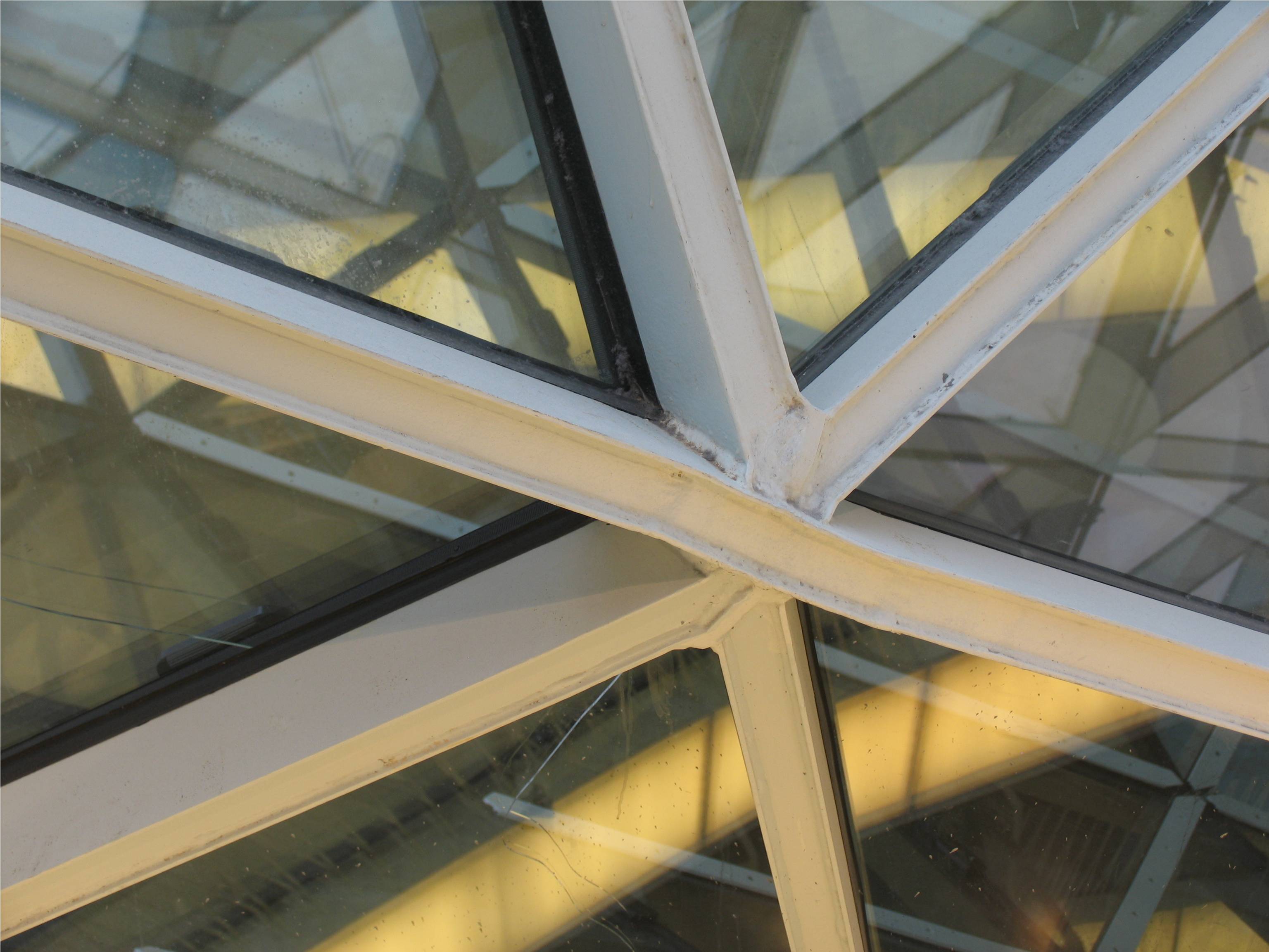
At first sight the roof of the shopping center in the Palaisquartier in Frankfurt has the looks of a nonstandard structure. But look carefully, the detail is welded with very low precision. In the design stage there was the nonstandard concept design of the renowned Italian architect Massimiliano Fuksas, there had been an intentional 3d wireframe mesh, but it was erroneously not executed using a precisely controlled CNC production process. Apparently the steel structure was manually drawn in 3d, not generated by scripts as it should have been. Many of the steel components were cut to length on site, the pieces were welded together on site in an extremely brutal fashion.  I feel obliged to show this example for educational reasons, not to blame anyone in this project, not the architect, not the engineer, not the manufacturer. But it is obvious that something went wrong. The link between the file and the factory was broken. There should have been an immediate link from a scripted high precision detail to the with high precision CNC produced components, to be dry assembled on site with zero tolerance. It should absolutely have been avoided to be welded on site since that introduces so much imprecision. Unfortunately, I have experienced a similar problem while building the CET in Budapest. In much the same way that the construction designs of the Bird´s Nest and the Water Cube in Beijing have been compromised by a traditional construction approach, also the execution of the CET has regrettably been subject to old school construction methods. The problem is how to secure a sustainable nonstandard design and building process. The solution is to secure an unbroken link from BIM to CNC production to dry montage of the unique pieces of the 3d puzzle. Breaking the direct link, that is not transmitting the exact data from the “design” phase into the “build” phase of the design & build process, is a recipe for putting back innovation in the building industry.

007 | LIWA tower | BIM

007 LIWA Tower BIM

LIWA tower | design Kas Oosterhuis / VAA.ONL | completed 2013 Abu Dhabi

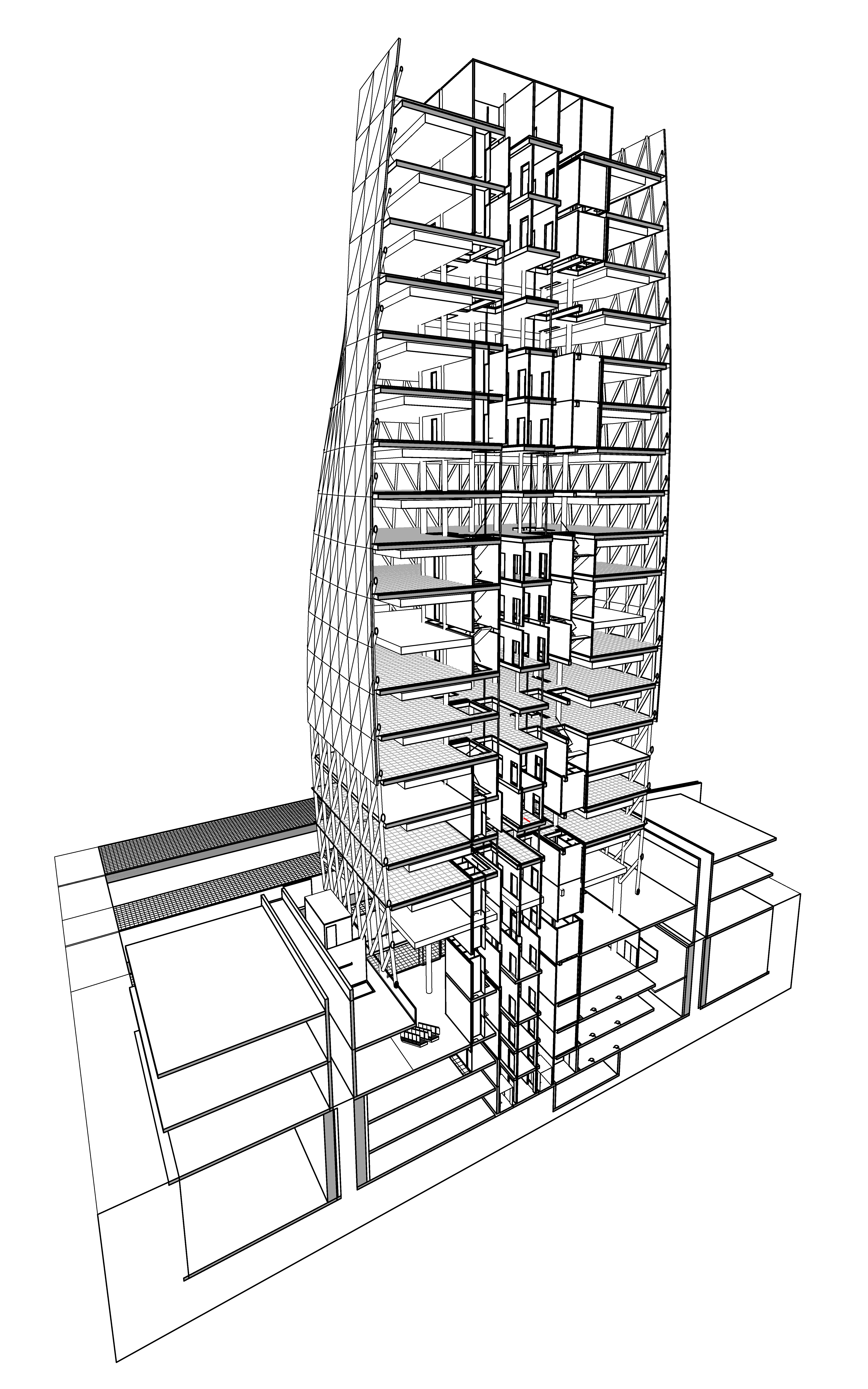
In 2006 ONL has won the design for the Al Nasser Headquarters tower in Abu Dhabi in the United Arab Emirates via an invited international competition. The client Mr Al Nasser owns a steel company and has chosen ONL´s iconic design, by far the most challenging of the competition entries, as he liked the exposed nonstandard steel structure inside and the metal duotone finishing of the exterior facade panels. Only in the final design stage the client as represented by Northcroft Middle East realized that all steel components and all windows are indeed different in shape and dimensions. They were fascinated by this fact but at the same time worried if this would be feasible within the strictly commercial budget they had defined for this project. Thanks to the precise control ONL successfully has monitored on the data as extracted from the Revit BIM model they were convinced that it was feasible indeed. The smart BIM model has served many purposes. In the first place ONL appointed no more then one single highly skilled architect, the young Gijs Joosen MSc, to be the executive architect and the BIM modeller in one. No information was lost in translation. The BIM model allowed for tweaking the curvatures of the shape of the office tower until the requested maximum GFA was reached, while maintaining the uniqueness of all constituting components and the unique configurations of each office floor. Any change in the curvature affects the square footage of each floor and hence the allowed GFA. Furthermore it facilitated to communicate with high precision with the local architects ACG who were responsible for acquiring the building permit and responsible for the calculations of the steel structure. The Al Nasser HQ is now under construction and will be finished in 2013.

PS: the building is now renamed into the LIWA tower

006| Bálna BIM

006 | Bálna BIM

CET / Bálna on Autodesk Revit cassette cover | 2010

In summer 2007 ONL, together with the Hungarian project developer Porto Hungary Kft, has won an international tender to build a cultural mixed use center in the heart of the Pest side of Budapest, on a truly unique location at the banks of the Danube. The nonstandard design includes the conversion of the old Közraktárak warehouses, and completes it with a bold new structure, jutting out southbound towards new developments along the river. The building is scheduled to be completed by the end of 2010. The design stands out as an uncompromising nonstandard design. The notion of nonstandard was already promoted by a small but influential cultural elite in Budapest in the first decade of 21st century, I was interviewed for the magazines Atrium and Octogon. There were also designs developed for Budapest by other players in the international arena, there was a kidney shaped office building by Zaha Hadid for Tervita Square and another office building design by Asymptote in the odd form of two giraffe blockheads. These projects stranded because of their financial and urban arrogance, ignoring local rules and commercial financial constraints. I did not fall into that trap, since I respected the urban guidelines and the available budget. I was able to develop a feasible nonstandard design within these severe constraints. One of the strongholds of the success formula was the Building Information Model that was modeled in Revit, allowing to work in real time connected work groups in ONL´s Budapest and Rotterdam offices. Eventually ONL was rewarded the Autodesk Revit Experience Award in fall 2008, by and large because the complex triangulated mesh was successfully imported in the otherwise starched parametric Revit software and used to model the steel structure. One person in Budapest would control all concrete components, another the old warehouses, a third all installations, while in Rotterdam the complexity of nonstandard geometry was controlled. The four work groups updated their work on a daily basis. Instant updating was in principle possible but would have taken too much transmitting time, and hence would have slowed down the work. Autodesk was happy with the achievements, which made them decide to obtain one of the CET renders in the opening window of Revit version 2010, also appearing on the cover of the Revit 2010 CD cassette.

005 | Grasshopper

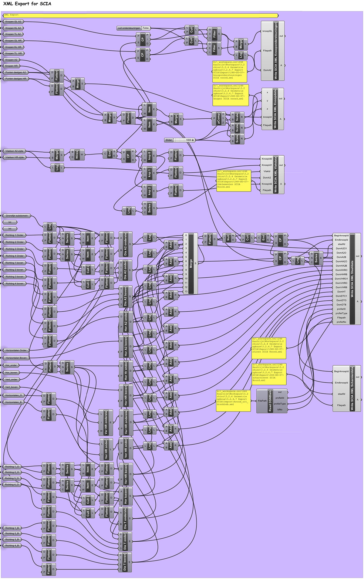
Grasshopper script_Sound Barrier Haarrijn_VAA.ONL 2010

005 Grasshopper script Haarrijn

A typical procedure in VAA.ONL / Hyperbody designs is to define the feature lines of the whole structure first, then define the point cloud of reference points, and then augment the points with further details for the physical nodes. The data produced by the Grasshopper scripts are directly used for the CNC production of the constituting building components. The Haarrijn sound barrier features s dense stainless steel mesh along the A2 side and 6mm solid natural aluminium plates at the other side. As in all VAA.ONL designs all sides are considered to be front sides, and are treated as such. For the Haarrijn project we have taken the responsibility for the structural design as well. In collaboration with Arcadis we have set up an immediate link between the geometry of the designer and the caculations of the structural engineer. One of the clues for the evolutionary success of synthetic architecture is the direct link in the early design process between the most relevant disciplines. In the Haarrijn project we took the initiative to set up the direct link between our Grasshopper file and the structural engineers SCIA file. Grasshopper exports coordinates and other on beforehand agreed data to XML. SCIA reads the XML file, changes some data on the basis of the calculations, and exports the new data to XML which are read again by Grasshopper. This direct facilitates an intense feedback loop between designer [geometry] and engineer [calculation]. the feedback loop is itinerated many times as to reach the optimum in kg´s steel, number of nodes, foundation frequency and costs.